Paths Tab
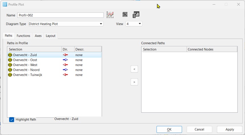
- Paths in the diagram
- The list displays all paths which the profile plot is made up of. The single paths listed here are linked to each other. The interconnect point is always a supporting node in the selections.
- In the column "Selection", the names of the paths which the diagram is made up of are specified.
- In the column
"Direction" the orientation of the individual path in the diagram concerning
the axis length is specified. The path is drawn from the interconnect point in
positive direction, if the blue arrow points to the right
 . The path is drawn from the
interconnect point in negative direction, if the red arrow points to the left
. The path is drawn from the
interconnect point in negative direction, if the red arrow points to the left
 . By double-clicking in the
column, the orientation changes.
. By double-clicking in the
column, the orientation changes.
- The text axis on which the node names of the paths are given is named in the column "Text".
- In the column selection, the symbol displayed gives information about the condition the path in the network. The symbols have the following meaning:
- Symbol Meaning
 The path was found in the network
and is represented in the diagram. This symbol also appears if no results were
calculated but that path exists in principle.
The path was found in the network
and is represented in the diagram. This symbol also appears if no results were
calculated but that path exists in principle.
 The path from the initial to the
end node over the sub-nodes was not formed and the path is not represented.
Possible causes:
The path from the initial to the
end node over the sub-nodes was not formed and the path is not represented.
Possible causes:
- The path is locked and is not available for current calculation.
- The path is no longer valid because less than 2 nodes are present.
- The path was interrupted by constructional changes.
 The path is not formed because
the parent path is invalid. The path is not represented.
The path is not formed because
the parent path is invalid. The path is not represented.
- < – Transfers the selected path selection from the list transfers "connecting paths" to the list "paths in the diagram". When it is transferred, the connecting path is connected to the named connecting nodes in the path selection in "paths in the diagram".
- > – Removes a path selection from the list "paths in the diagram".
- Connecting paths – List of the path selections, which have a common connecting node with the selected path from the path list (left list). The name of the connecting node is stated in the second column.